Co-located transmitters and receivers degrade each other through reverse intermodulation, co-modulation, and receiver de-sense, and antenna isolation is the first line of defense. Here is how vertical clearance, radiation patterns, filtering, and RF-over-fiber remoting combine to keep a shared site clean.
What Is Co-Site Interference and Why Does Antenna Isolation Matter?
Co-site interference happens when several transmitters and receivers share the same tower, rooftop, shelter, or enclosure and begin to degrade each other's performance. The coupling path is almost always antenna-to-antenna: energy radiated by one antenna gets picked up by another, travels down the receive line, and hits a front end that was never built to handle that much out-of-band power. Antenna isolation, measured in dB from the interferer port to the victim port, is the most important passive defense you have. Every extra dB of isolation buys headroom for the receiver, the power amplifier, and the filters behind them. I treat isolation as a budget line item, not an afterthought.
How Do Spatial Separation and Vertical Clearance Improve Isolation?
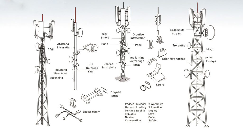
Isolation comes down mostly to two things: how far apart the antennas are and what wavelength you're working with. Antennas that sit closer together couple more energy, and propagation loss drops as spacing shrinks—so the same physical gap behaves very differently at 100 MHz than it does at 15 GHz. The planning reference people cite most often is Motorola R56 (2005), Section 8.4.1, which links clear vertical separation to approximate isolation for stacked transmit and receive antennas. One detail that gets botched constantly when people sketch out a tower layout: clearance is measured from the tip of the lower antenna to the base of the upper antenna, not from center to center.
| Clear vertical separation | Approximate isolation | Typical use |
|---|---|---|
| 3 m (10 ft) | About 45 dB | Moderate-power VHF/UHF co-location |
| 6 m (20 ft) | About 55 dB | High-power FM or dense multi-radio sites |
| Minimum 30 dB (LMR guideline) | Interferer port to victim port | VHF/UHF land mobile radio on one site |
Those figures are planning guidelines, not guaranteed specs for every frequency and antenna combination. For VHF and UHF antennas sharing a site, the land mobile radio (LMR) convention sets a floor of 30 dB isolation from the interferer port to the victim port, and the horizontal and vertical separation distances are chosen to hit that number. A quick sanity check shows why the margin matters: a 500 W FM transmitter runs at +57 dBm, and even with 55 dB of isolation, the illustrative power arriving at the receiving antenna connection is still around +2 dBm. That's well above a typical receiver's sensitivity floor—which is exactly why filtering and frequency management come into play after you've settled on spacing.
How Do Reverse Intermodulation Products Degrade Co-Located Receivers?
When you put two or more active transmitters close together, their signals mix in each transmitter's output stages and produce reverse intermodulation products (IMPs). The third- and fifth-order products are the ones to worry about, since they can land inside a receiver's pre-selector passband even when the fundamental frequencies are far apart. Once they get in, they push the automatic gain control down, saturate the input stage, and set off reciprocal mixing, where local-oscillator phase noise swamps the desired signal. What you actually notice is a noise figure that quietly degrades on a link that used to work fine—often right after someone adds a new radio to the site.
Co-modulation is basically the same problem wearing a different hat. In this case, one transmitter's signal makes its way into a second transmitter's output amplifier, and the two mix right there in that stage, producing unwanted products much like reverse intermodulation does. Receiver front-end de-sense works the same logic from the other direction. A strong out-of-band carrier compresses the first LNA, cutting gain and sensitivity across the band you actually care about—and in extreme cases, that energy can permanently damage the LNA. Antennas only help a little here. They act as weak passive bandpass filters, so when the frequencies are far apart they do give you some out-of-band suppression, but the effect is modest, varies from antenna to antenna, and should never be treated as your primary mitigation.
What Role Do Antenna Radiation Patterns and Array Design Play?
Radiation patterns can give you isolation that spacing alone won't. A vertical half-wave dipole has a null right along its vertical axis, so if you stack two in-phase dipoles about half a wavelength apart, the array factor adds cancellation above and below the stack. At 100 MHz, where the wavelength is about 3 m, a two-bay FM design might put the feedpoints roughly 1.5 m apart, with each dipole about 1.4 m long. That same geometry also splits 500 W into roughly 250 W per dipole, which shifts the interference math right at the source. The trap is treating any of this as a fixed dB bonus. The extra isolation from array phasing isn't a fixed number, and you shouldn't just add it to the 55 dB guideline—it has to be modeled or measured for the specific stack you're working with.
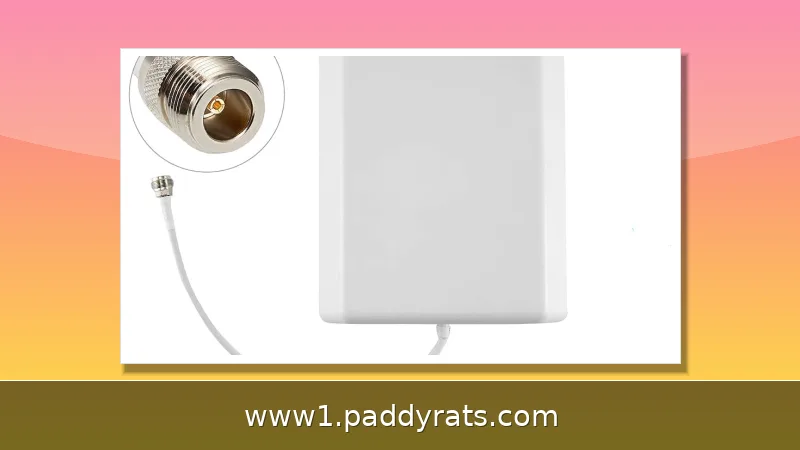
Huawei's March 20, 2019 white paper includes a convenient planning formula for co-locating NR with other radio access systems: Iv [dB] = 28 + 40 × log(dv/c) + delta, where dv is the vertical distance and c is a reference constant. It's a quick way to sanity-check a proposed stack before you commit to steel, but I treat it as a cross-check against measured data rather than a replacement for it—the formula gives you a starting point, and the site survey gives you the truth. Another caution I've learned the hard way: you can't assume how a cellular panel will respond at FM frequencies without antenna data or an actual measurement sweep. A panel that looks like a great filter on paper at 900 MHz or 1.8 GHz may behave very differently down around 100 MHz, where its pattern and match can shift in ways the datasheet never shows.
How Do Receiver Filtering and RF-over-Fiber Antenna Remoting Add Isolation?
Receiver filtering is your defensive move, and it sits after the antenna but before the most fragile part of the chain. Band-selective filters, duplexers, and pre-selectors attenuate unwanted carriers before they reach the LNA, so a strong off-channel signal can't push that first amplifier into compression and drag the receiver's noise figure down with it. This protection matters most in dense co-site environments, where a nearby transmitter might be running hundreds of watts while the victim receiver is trying to pull in a whisper. On the transmit side, the logic flips. Filtering ahead of the power amplifier cleans up sideband content and keeps the transmitter's own spectral skirt tidy, but it does nothing for multi-transmitter IMPs, since those products get mixed inside the output stages themselves and never pass through a filter on the way out. I keep those two use cases separate in every design review, because conflating them gives you filters that look right in a block diagram and accomplish nothing in the field.
| Filter Location | What It Addresses | What It Cannot Fix |
|---|---|---|
| Receive path (before LNA) | Unwanted carriers, compression, de-sense | In-band interference already inside the passband |
| Transmit path (before PA) | Sideband content, spectral emissions | Multi-transmitter IMPs generated in output stages |
RF-over-fiber (RFoF) antenna remoting takes a different route: it physically separates the radios from high-mounted antennas, providing RF isolation and minimizing intermodulation when TrellisWare, Persistent Systems, or Silvus radios share a site with SATCOM, SINCGARS, or EW emitters. The loss numbers are compelling. Fiber runs about 0.7 dB/km, versus roughly 1.2 dB per meter for 0.25-inch coax at 15 GHz, and RFoF systems cover 10 kHz to 60 GHz bi-directionally with SFDR above 110 dB/Hz. Frequency management remains the cheapest tool of all: spectral separation between networks lets normal pre-selection filtering protect receivers without new hardware.
How Should Antenna Isolation Be Tested and Planned on Site?
Measure isolation between each transmitting antenna and every other antenna, not just the obvious pairs. Include the actual transmission-line losses on both the transmit and receive paths, because those losses are part of the real isolation budget and ignoring them makes field results look worse than the design predicted. The dominant factor is proximity: the further apart the elements, the better the isolation, and that relationship is what the measurement should confirm.
Type approval may not cover receiver performance, so isolation testing during design prevents field issues and market rejection later. Collocation interference analysis is done site by site, because equipment, design parameters, and antenna configurations vary widely enough that a template answer is usually wrong. The limitations deserve equal weight: Motorola figures are guidelines, not guaranteed isolation, array phasing gains are not a fixed dB number, and filtering reduces power after the antenna without changing the incident electromagnetic signal. Treat every number in this article as a starting point for your own measurement plan.
What Is the Minimum Recommended Isolation for Co-Sited LMR Antennas?
For land mobile radio systems operating in the VHF and UHF bands, published guidelines recommend keeping at least 30 dB of isolation between co-sited antennas, measured from the interferer port to the victim port, for equipment sharing the same site. Those same guidelines pair that figure with specific horizontal and vertical separation distances meant to get you there in practice. I treat 30 dB as a floor for coexistence, not a comfort target—it is the point where the radios can generally hear each other without obvious trouble, not the point where they perform at their best. Once a site carries high-power transmitters or several radios packed into a single enclosure, that margin starts to feel thin, and the 45 dB and 55 dB vertical clearance figures from Motorola R56 become the more realistic planning anchors. Treat the numbers as starting points for the design, then confirm them against the actual equipment and antenna layout on site.
How Much Antenna Separation Is Needed for Co-Located Radios?
The real-world answer hinges on frequency, transmit power, and antenna type, but the planning baseline is well established. Motorola R56 (2005), Section 8.4.1, calls for 3 m (10 ft) of clear vertical separation to achieve roughly 45 dB of isolation, and 6 m (20 ft) to reach about 55 dB. Note that clearance is measured from the tip of the lower antenna to the base of the upper antenna, and these figures are antenna-to-antenna planning estimates—not guaranteed specifications for every frequency and antenna model. Frequency is the variable that trips people up most. As you move lower in the spectrum, the wavelength grows, so the same physical gap represents fewer wavelengths of separation, and isolation at a given spacing typically suffers. That is precisely why VHF sites often need more clearance than the table suggests, while UHF and higher bands can sometimes get by with less than the guideline predicts.
What Causes Interference Between Co-Located Transmitters?
Most people picture interference as something that happens out in the air, but a lot of it actually starts inside the transmitters themselves. When two or more transmitters sit close together, their signals mix in each other's active output stages, producing what are known as reverse intermodulation products. Those third- and fifth-order IMPs can land right inside a receiver's pre-selector passband and desensitize it — through AGC drive-down, input saturation, or reciprocal mixing, where local-oscillator phase noise swamps the wanted signal. The practical fix is a layered one: isolation first, then filtering, then spectral planning — applied roughly in that order of cost effectiveness. | Mechanism | Where It Originates | How It Degrades the Receiver | |---|---|---| | Reverse intermodulation (3rd/5th order) | Mixing in active transmitter output stages | IMPs fall in the pre-selector passband; AGC drive-down, saturation, reciprocal mixing | | Co-modulation | One transmitter's signal hitting a second transmitter's output amplifier | Mixing product raises the noise floor | | Front-end de-sense | Strong out-of-band carrier compressing the first LNA | Lower gain and sensitivity; extreme cases can permanently damage the LNA |
How Is Antenna Isolation Measured on a Device With Multiple Transmitters?
For each transmitting antenna on the platform, isolation is measured between that antenna and every other antenna on the platform—not just the nearest neighbor, and not just the obvious pairing. Proximity is the dominant factor: the further apart the elements sit, the weaker the coupling and the better the isolation. One detail people get wrong is that transmission-line losses on both the transmit and receive paths must be folded into the calculation or measurement; skip them and the result overstates the protection the receiver actually sees. I run the sweep with the real cabling and the real antenna installations in place. A bench measurement with short jumpers tells you almost nothing about what happens on a tower, where long coax runs and imperfect connectors eat into the margin you thought you had.
Frequently Asked Questions
How much antenna separation is needed for co-located radios?
Motorola R56 (2005) Section 8.4.1 gives planning guidelines for vertically separated transmit and receive antennas: 3 meters (10 feet) of clear separation yields about 45 dB isolation, and 6 meters (20 feet) yields about 55 dB. These are antenna-to-antenna estimates, not guaranteed specifications for every frequency and antenna model.
What causes interference between co-located transmitters?
When two or more active transmitters are close together, their signals mix in each transmitter's output stages, producing reverse intermodulation products. Third- and fifth-order products can fall inside a receiver's pre-selector passband and desensitize it through AGC drive-down, input saturation, or reciprocal mixing.
What is the minimum recommended isolation for co-sited LMR antennas?
Guidelines for land mobile radio systems in the VHF and UHF bands recommend a minimum of 30 dB isolation between co-sited antennas, measured from interferer port to victim port, for equipment on the same site. The guidelines also specify horizontal and vertical separation distances to achieve this figure.
How is antenna isolation measured on a device with multiple transmitters?
For each transmitting antenna, isolation is measured between that antenna and every other antenna. The main factor affecting isolation is proximity: the further apart the elements, the better the isolation. Transmission-line losses on both the transmit and receive paths must be included in the calculation or measurement.